SpiKeGuard™ Insulation System.
Industrial electric motors are known for being quality products that offer long, trouble-free operation. This is as true today as ever before. The difference, however, is that today, with the proliferation of AC motors in adjustable-speed drive systems, there is greater awareness of potential hazards to motor windings.
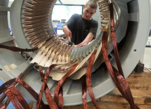
Winding damage too often?
Damages arise from the voltage spikes generated by the increasingly popular pulse-width-modulated (PWM) regulators, or inverters, that use IGBT power transistors. The growing awareness surrounding this issue often focuses on the insulation of the motor, sometimes on the insulation of the winding wire itself, and sometimes on the entire insulation system.
SPIT's approach, through our SpiKEGUARD™ insulation system, is clearly focused on the total system - from the original design as conceived by the manufacturer, to rewinding and beyond. This includes extensive testing of all components, both individually and in cooperation with winding material manufacturers. In addition, all stators are tested to ensure manufacturing quality, and lifetime testing is conducted to ensure future development.
The purpose of this blog is to explain the elements of SPIT's "systems approach. Additional information and definitions of key terms are included in the appendix at the end of the article.
Industrial electric motors are known for their durability. However, with the advent of modern variable speed drives, the risk of winding damage increases. SPIT solves this problem holistically. Check out its core elements here.
SpiKEGUARD™ Element 1 - corona resistant winding wire
The combination of frequency converters, cables and motor can lead to high voltage spikes on the motor windings.
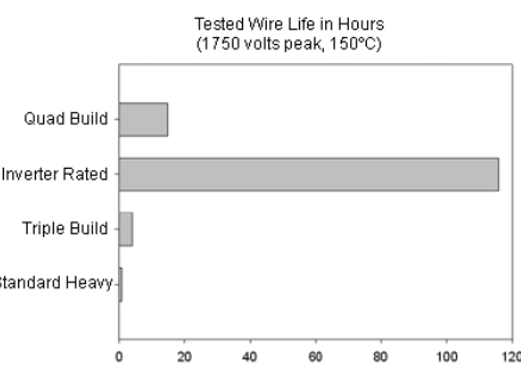
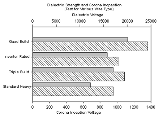
MEASURE VOLTAGE IN THE MOTOR. Drives with higher supply voltages between 500-700 VAC, cause high voltage spikes at the motor terminals. The exact height depends on the drives, the cable (length) used, motor and application. However, the voltage "seeing" the winding wire, and not the voltage at the terminals, is the critical point. Tests are usually performed by twisting two pieces of wire and applying the high test voltage from one wire to the other. Of course, this situation should never occur in a motor if it is properly designed and manufactured. Voltages at the motor terminals are distributed to many windings of wire in a coil in the motor, which are then distributed (although unevenly) to many windings in each coil. The goal in design is to ensure that the voltage between two wires remains below safe levels, taking into account their insulation.
DIFFERENT WIRES FROM DIFFERENT MANUFACTURERS. Not only is the wire different, but manufacturers are introducing new versions or generations of wire. To further complicate the issue, there are no standards for testing or rating wire or any other insulation component for use on regulators. SPIT works closely with wire manufacturers in developing new generation products to ensure that they work well with other materials and manufacturing processes. SPIT also conducts its own testing to supplement and verify data from wire manufacturers.
FOUTEN IN DE EERSTE WINDING. Er is veel discussie over ongelijke spanningsverdeling in de spoelen (of de zogenaamde eerste winding fouten) in door omvormer-gevoede motoren. Uit tests en ervaring van SPIT is gebleken dat dit een non-issue is voor kleine motoren (<IEC280), iets dat ‘kan gebeuren’ maar bijna nooit gebeurt. Zelfs motorstoringen die oorspronkelijk werden toebedeeld aan windingsluiting, blijken vaak andere oorzaken te hebben bij nadere analyse. Bij grotere motoren is het wel een probleem. Hier hebben vrijwel alle gerenommeerde motorfabrikanten manieren om met dit probleem om te gaan. Over het algemeen komen fouten in de eerste winding vooral voor bij regelaars met een lage schakelfrequentie of een soort ‘just-in-time’ schakelpatroon. Hierdoor kan de puls dieper in de spoel doordringen.
WHY DO SOME MANUFACTURERS CLAIM GREAT IMPROVEMENTS WITH THE NEW WIRE TYPES? As the previous charts have shown, the advantage of "special" winding wire lies in situations where the wire is exposed to high spikes from the inverter. An insulation system, if properly designed, minimizes the wire's exposure to this high voltage. Wire with an inverter specification should extend motor life when used on an inverter in a drive system. It should also provide a margin of safety. However, it should not be relied upon as the sole source of protection against potential voltage spikes. If replacing the wire alone results in significant life improvements, it could be an indication of a more serious problem in fundamental motor design and manufacturing methods.
SpiKEGUARD™ Element 2 - Inserting coils into the stator core
Techniques and processes used to insert or slide the winding wire into the stator core are more important than the coating used on the wire. The coating cannot be effective if it is damaged or notched. Special attention must be paid not only to the equipment and processes used in motor manufacturing, but also to the considerations made in the development of new wire coatings. A balance must be achieved when considering corona resistance, flexibility and abrasion resistance.
METHODS FOR WINDING. Because the voltage is distributed over the windings, it is important that the winding is even and that the wires do not cross each other randomly. There are several ways to achieve this using different types of winding jigs and coil insertion splines, or with manual winding processes. The trade-off here is wire position versus wire damage. SPIT has selected high-quality automatic winding jigs and inserters, built to our specifications, for the production of smaller motors. Larger motors are wound by hand or machine, depending on the design. In each case, care is taken to ensure the best quality. This includes special training for production staff involved in winding motors with inverter power.
Some manufacturers use so-called "in slot" winders. In this winding method, the wire passes through "needles" that feed the wire through the narrow slot opening directly into the slot. But the wire must run back and forth along the length of the stator and around the tin fingers at each end for each winding. Compare this to wire smoothly coming off a coil on a jig and inserting the finished coils all at once. There are obvious trade-offs. The stated advantage of in-slot winding is the ability (in theory) to "automatically position" or layer the wire in the slot, keeping the beginning and end of the spool as far apart as possible. Because the wire can move freely, in practice the coils are never perfect. And as mentioned, orderly winding is the goal of any method.
The point is that there is no clear "best way" to wrap stators in everyday production. If there were, everyone would use it. The key to success is to select a proven method, design it and perfect it. The results will speak for themselves.
INSULATION MATERIALS. The best winder cannot make up for poor core packages or groove insulation that is not suitable for the application. SPIT uses a variety of high quality insulation materials (polyester films and laminates such as natural Mica, DMD, NMN) specifically matched to the production process and insulation class.
SpiKEGUARD™ Element 3 - Insulate all critical areas
SLOT INSULATION. It is critical that all the spurs of the coils be properly jacketed depending on their location and the voltage to which they will be exposed. These spurs may need to run over coils of other phases where voltage differences will be greatest. Relying solely on wire coating would be a mistake. To adequately protect these spurs, it is often necessary for the insulation tube to extend from the terminal board to (far) into the stator slot.
PHASE INSULATION. Phase insulation can be the most difficult part of the entire winding process, and crucially important. It is the only insulation component specifically designed to separate coils and wires of different phases (where the greatest potential differences are present). Some manufacturers have cut back on this very thing. Thinner materials (or no insulation at all) or improperly placed phase insulation can go unnoticed in motors intended for low voltage or sinusoidal voltage only. But today, more and more motors are connected to an inverter. While some manufacturers applied intermediate phase insulation in motors that originally did not have it, SPIT was busy looking for ways to improve our phase insulation, which has always been applied by us.
CONNECTION INSULATION. There are many ways to make and isolate the connections between suckers and coils. SPIT Always keeps looking for improved methods. But for now, connections are still provided with tape or insulating tube to fill and protect them, providing a high level of electrical and mechanical strength. Connections that pierce through the insulation are a common problem with motors on an inverter, but also a point you don't have to worry about with motors that have been redesigned by SPIT.
BANDING AND INTERMEDIATE BLOCKS. SPIT ensures that the windings are properly supported and secured, because different vibration patterns can occur in inverter-driven motors than motors connected directly to the grid.
THERMAL CONSIDERATIONS. Because of harmonic losses, inverter-controlled motors can get hotter than when powered directly from the grid. Make sure the motor's cooling system (often the fan and fins) is sufficiently efficient.
SpiKEGUARD™ Element 4 - Impregnation
To be effective, the resin must penetrate well into the slots and between the threads. In round-wire wound motors, the resin replaces the air around and between the wires. This reduces the amount of air that can ionize or convert to ozone. A thicker coating of resin on the outside of the coil does not mean that the resin has actually penetrated the coil. Care should also be taken to ensure that the correct resin is chosen for the type of wire being used. Tests have shown that some resins actually shorten the life of inverter-rated wires, even though they are chemically compatible.
The bottom line is that SpiKEGUARD™ represents an insulation system consisting of quality Class F and Class H components, designed to work together and be properly implemented. It is a system suitable for inverters in more ways than one.
DEFINITIONS
Control: also called inverter or converter, is an electronic device that converts an AC or DC input current into a controlled AC output voltage or current (as defined in various IEC, NEMA and IEEE standards)
Corona: a sparking discharge produced near a conductor, without strongly heating it, due to ionization of the air around the conductor caused by a voltage gradient exceeding a certain critical value.
Corona inception voltage: the lowest or initial voltage at which continuous corona occurs.
Drive: the equipment used to convert electrical power into mechanical power suitable for operating a machine. An inverter is a combination of a power converter (controller), motor and any auxiliary equipment mounted on the motor (as defined in IEC, NEMA and IEEE standards).
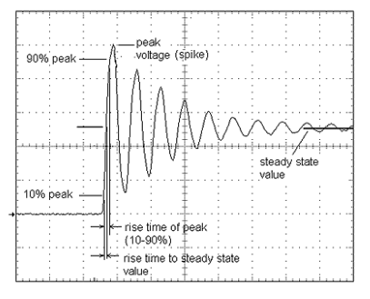
dU/dt: literally delta (change in) volts divided by delta (change in) time. It is the slope or rate at which the voltage changes over time of a voltage pulse or waveform. It is normally measured in volts per microsecond (V/µs). A modern IGBT drive has a value of somewhere between 6 to 10 kV/µs.
IGBT (isolated gate bipolar transistor): a semiconductor component widely used in power electronics, especially in situations requiring high efficiency and fast switching. It combines the simple gate-drive characteristics of metal-oxide-semiconductor field effect transistors (MOSFETs) with the high current and low saturation voltage capability of bipolar transistors. used in modern PWM inverters.
Nanosecond (ns): One billionth of a second.
Ozone: a light blue gas with a distinct, pungent odor. A form of oxygen,03. This gas will react with certain organic compounds.
Peak voltage: the instantaneous peak value, normally the maximum voltage value.
PWM (pulse width modulation): A control method that varies the pulse width to produce a desired waveform.
Rise time: the time interval of the leading edge between when the value reaches a specified lower and upper limit. This can be 10% to 90% (normally) of the peak value, or of the steady-state value. Both definitions are used, leading to frequent confusion. IEC uses the steady-state value. Values of 50-70 ns (nanoseconds) are common for the newest IGBT modules; values of 200-300 ns are still mainly found on older inverters.
Voltage spike: a distortion (usually assumed to have a relatively high voltage) in a voltage pulse of relatively short duration, superimposed on an otherwise regular or desired waveform.
How does the inverter - motor combination work?
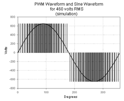
The abbreviated version of how an AC PWM variable frequency drive works is as follows. As a first step, the inverter rectifies the AC mains voltage to a DC voltage. This is called the intermediate circuit. Then, using power electronics such as transistors or SCRs, the controller produces a stream of pulses that "simulate" the desired voltage and frequency. The image on the right shows a sine wave (AC) line voltage, on top of the pulsed inverter output, or 'simulated' AC. The number and width of the pulses varies or is modulated (PWM) so that if you were to average (or mean, RMS) the pulses, you would get the same value as the sine wave. Notice that the pulses have the same height. This is true because the DC voltage that the control uses to make these pulses is nearly constant if the AC current to the control has a constant value.
Now look at the image to the right, which shows an oscilloscope image of pulses from an inverter. The bottom pulses are the pulses coming directly from the inverter. They look very square. The top pulses, however, look very different. They show what pulses can look like at the motor end of the cable. The overshoot or "surge" high voltage spikes that occur at the motor end are the source of problems for some insulation systems. For motors rated at 690V, these spikes quickly exceed 3,300V, causing insulation problems in motors with inappropriate windings.
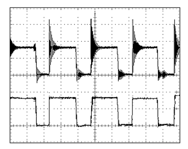
The cause of this oscillation can be explained in several ways. It can be seen as the electrical response of the "circuit" consisting of the inductance, resistance and capacitance of the motor and cable to the pulse. Or it can be seen as the interaction of pulses reflected from the motor and pulses coming from the controller. Either way, the result is a peak voltage that is about twice as high (often even higher) than the pulse delivered by the controller in the first place, with the addition of high-frequency 'oscillation' on top.
Contact
Want to know more?
We would love to hear what your inventory management needs are. With our experience and our extensive workshop, we can help you in the way that suits your business.